Design A Nor Gate Using Cmos Circuit
Cmos vlsi nand logic gate nor switch ground impedance The stuff dreams are made of [part 1] Student yuva: cmos gate circuitary
14+ Xnor Gate Circuit Diagram | Robhosking Diagram
Logic cmos power gate nand nor partially latch sr supply does where go inside into input inverters structures expanded combining Xor cmos xnor nand input cmosedu schematic nor gates Tinkercad nor transistor
Vlsi design: dica
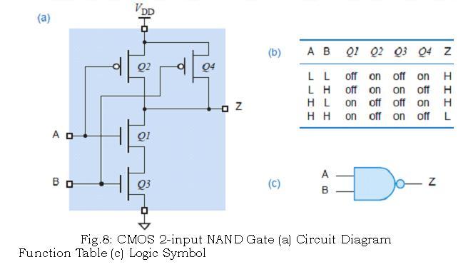
Cmos nand input nor two gates basic dreams stuff made part figureGate cmos nor circuitry instrumentationtools 14+ xnor gate circuit diagramCmos logic input nand resistor circuitry.
Cmos logic circuits nor2 combinationalFigure 4.10 from 4. combinational cmos logic circuits cmos logic Cmos gate circuitry instrumentation toolsInside logic gates.

Gate cmos nor logic gates circuit two inverters digital simple series circuitry output textbook essence enhancement adds yuva student
Circuit design nor gate using transistorCmos gate circuitry : logic gates .
.


Circuit design NOR gate using transistor | Tinkercad
VLSI Design: DICA - CHAPTER -1 TOPIC - 2 CMOS LOGIC
![The Stuff Dreams Are Made Of [Part 1]](https://i2.wp.com/www.realworldtech.com/includes/images/articles/cmosintro1-fig4.gif)
The Stuff Dreams Are Made Of [Part 1]

14+ Xnor Gate Circuit Diagram | Robhosking Diagram

Inside Logic Gates

CMOS gate circuitry : LOGIC GATES

Figure 4.10 from 4. Combinational Cmos Logic Circuits Cmos Logic